Quality and safety on every solar site

The safety practices we follow every day, and the civil and electrical tests that prove a solar plant is built right.

Safety on site

Safety is supervised daily

A safe site is a productive site. These six practices apply on every Solunar site, every working day.

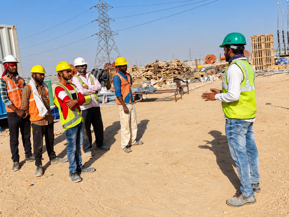
Toolbox safety talk with workers on a solar site
  • Dedicated safety supervisorPresent at every site, every working day.
  • Mandatory PPE for every workerHelmets, reflective jackets and safety shoes.
  • Daily toolbox safety talksA short safety briefing before work starts.
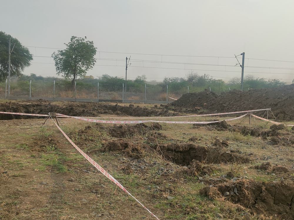
Barricaded excavation on a solar site
  • Safety induction for every workerEvery new worker is inducted before starting work.
  • First-aid kit on every siteKept ready at the site office for immediate care.
  • Barricading around excavationsOpen trenches and pits are marked and barricaded.
Civil tests

Civil tests on a solar power plant

These tests prove that the foundations and structures will hold the plant safely for its full life.

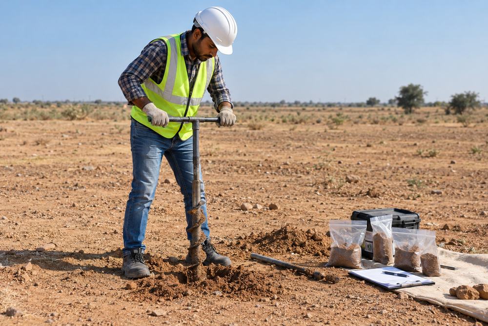
Engineer collecting soil samples with a hand auger on a solar site
Civil test 1

Soil investigation (geotechnical survey)

Before piles are designed, the soil is tested to understand its strength and type. The results decide pile depth and size, and soil resistivity values are used for the earthing design.

Why
Pile foundations must suit the actual ground conditions.
Reference
IS 1892:2021 (subsurface investigation) and IS 2131:2025 (standard penetration test)
Result
No pass or fail. Results are used for the pile and earthing design.
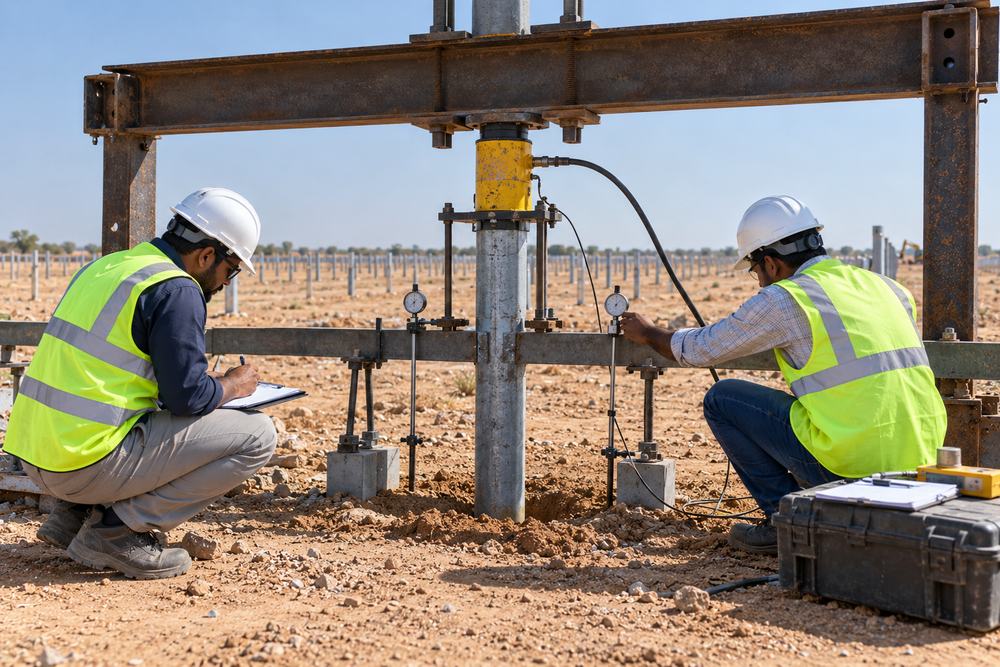
Pile load test with hydraulic jack and dial gauges
Civil test 2

Pile load test

Trial piles are loaded to check that they can safely carry vertical, lateral and uplift (pull-out) loads, including wind loads on the solar modules.

Why
Confirms the pile design before hundreds of piles are cast.
Reference
IS 2911 (Part 4):2013, covering vertical, lateral and pull-out load tests
Acceptance
Pile movement under test load must stay within the limit set in the design.
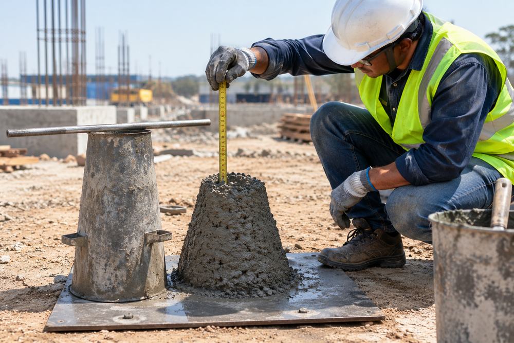
Engineer measuring concrete slump on site
Civil test 3

Concrete slump test

A quick site test that checks the workability of fresh concrete before it is poured into the pile holes.

Why
Concrete that is too dry or too wet leads to weak or honeycombed piles.
Reference
IS 1199 (Part 2):2018
Acceptance
Slump must match the approved concrete mix design.
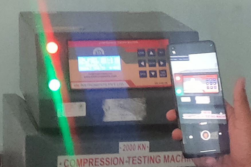
Concrete cube in a compression testing machine
Civil test 4

Concrete cube compression test

Concrete cubes are cast from each pour and crushed in a compression testing machine to confirm the strength of the concrete.

Why
Proves the concrete in the piles has the design strength.
Reference
IS 516 (Part 1/Sec 1):2021 for testing, IS 456:2000 for acceptance
Acceptance
Tested at 7 and 28 days. At 28 days the strength must meet the grade, for example 25 N/mm² for M25 concrete.
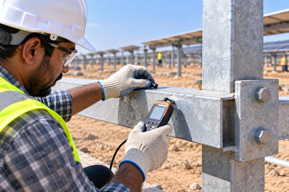
Measuring galvanizing thickness on a steel solar structure
Civil test 5

Galvanizing coating thickness test

The zinc coating on steel piles and mounting structures is measured with a digital coating thickness gauge.

Why
The coating protects steel from corrosion for the 25-year life of the plant.
Reference
IS 4759:1996 (hot-dip zinc coatings on structural steel)
Acceptance
Coating mass as per IS 4759 for the steel thickness, about 610 g/m² (roughly 85 microns) average for steel 6 mm and thicker, or higher if the project specifies.
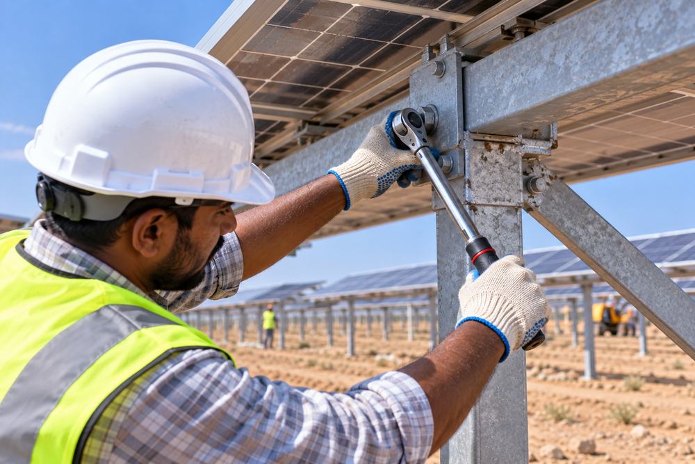
Technician checking bolt torque on a solar mounting structure
Civil test 6

Bolt torque check

Every structural bolt is tightened with a calibrated torque wrench and then marked, so a loose bolt is easy to spot.

Why
Loose bolts let structures move in the wind and can damage modules.
Reference
Structure designer's torque chart
Acceptance
Every bolt at the specified torque value, marked after tightening.
Electrical tests

Electrical tests before commissioning

These pre-commissioning tests prove that the plant is safe to energise and will generate as designed.

Engineer doing an insulation resistance test with a digital megger
Electrical test 1

Insulation resistance (megger) test

A high test voltage is applied to cables and strings to check that the insulation is healthy and there is no leakage to earth.

Why
Damaged insulation causes earth faults, inverter trips and fire risk.
Reference
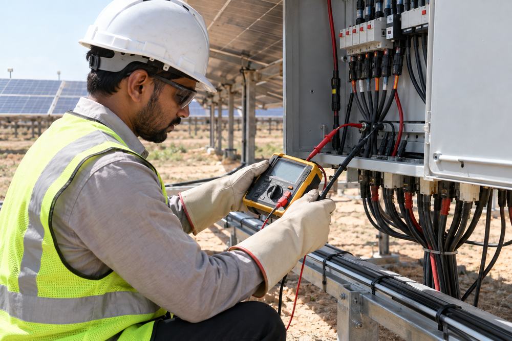
IEC 62446-1 (international standard for PV system testing)
Acceptance
At least 1 MΩ, tested at 500 V, 1,000 V or 1,500 V DC depending on system voltage (IEC 62446-1). Healthy new cables usually read in hundreds of MΩ, so any unusually low reading is investigated. Where the project sets a higher value, we test to that.
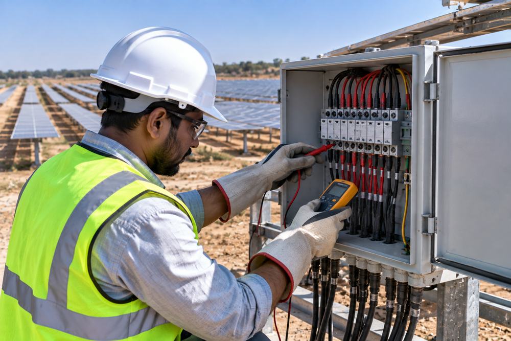
Technician testing a solar string at a combiner box with a multimeter
Electrical test 2

String open-circuit voltage and polarity test

Each string is checked for correct polarity and its open-circuit voltage (Voc) is measured before connection to the inverter.

Why
Reversed polarity can damage inverters. Wrong Voc shows a missing or faulty module.
Reference
IEC 62446-1
Acceptance
Voc close to the expected value after temperature correction. Strings in the same group should be within about 5% of each other.
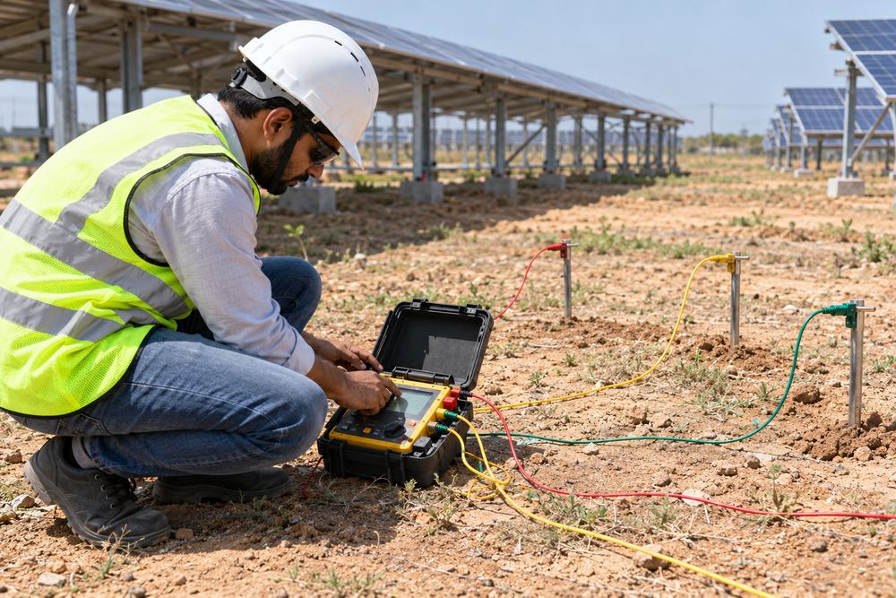
Engineer doing an earth resistance test with test spikes
Electrical test 3

Earth resistance test

The resistance of the earthing system is measured to make sure fault current and lightning have a safe path to the ground.

Why
Good earthing protects people and equipment.
Reference
IS 3043:2018 (code of practice for earthing)
Acceptance
Below 1 ohm for the main earth grid, the value most utility-scale solar specifications ask for, or lower if specified.
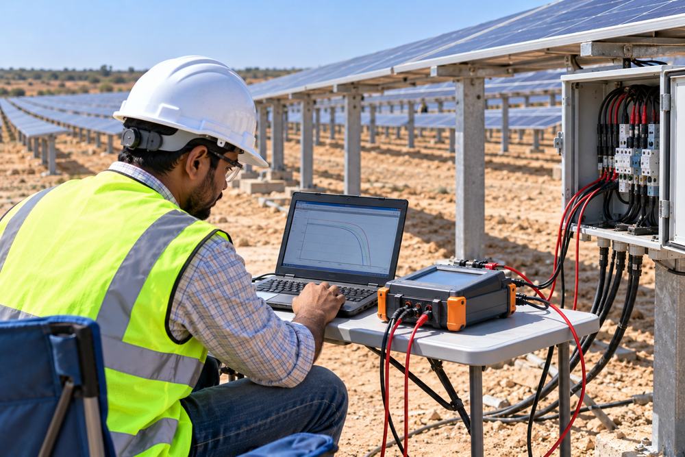
Engineer using an IV curve tracer connected to a solar string
Electrical test 4

IV curve tracing

An IV curve tracer measures the full current and voltage curve of each string and compares it with the expected curve.

Why
Finds shading, mismatch, damaged modules and wiring issues that simple tests miss.
Reference
IEC 62446-1, Category 2 tests
Acceptance
Curve shape and power close to expected values at standard conditions. Abnormal strings are checked and fixed.
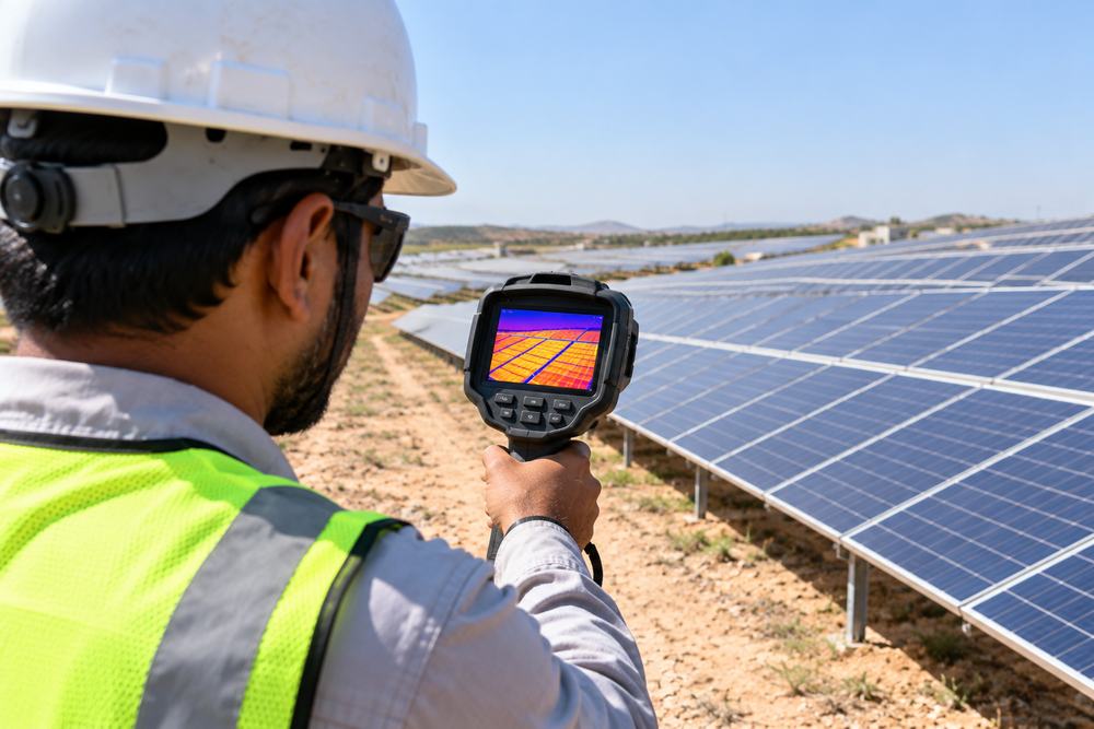
Engineer scanning solar panels with a thermal camera
Electrical test 5

Thermography (infrared inspection)

A thermal camera scans modules, connectors and combiner boxes while the plant is generating.

Why
Hotspots show faulty cells, loose connections and failing diodes before they cause damage.
Reference
IEC TS 62446-3 (outdoor infrared thermography of PV plants)
Acceptance
Hotspots of about 10 °C or more above neighbouring areas are investigated and fixed.
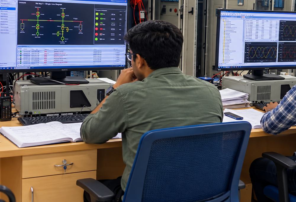
Engineers checking inverter and SCADA screens
Electrical test 6

Inverter and SCADA commissioning checks

Inverters, protection settings and monitoring signals are checked together before the plant is handed over.

Why
Confirms the plant runs, protects itself and reports data correctly.
Reference
Manufacturer procedures and project specification
Acceptance
All inverters, alarms and monitoring signals working and recorded.

The standards and values above are common references. The exact tests and acceptance values for each solar project are set by its technical specification. Tests are carried out by our team or through third-party laboratories, as the project requires.

Planning a solar project?

Share your scope and timeline. We will come back with availability and a quote, or send you our company profile.

Have land?

Planning a solar plant on your agricultural land or for your business?

Solar for landowners
Solunar engineer

Got questions?

Our engineers are one WhatsApp message away.

Chat with our team

Get our company profile

Share a few details and our team will send the Solunar Infratech company profile to you.